

Have you ever wondered if it is possible to build a simple amplifier of high sound fidelity? Have you thought if audiophiles are right claiming that quality must cost a fortune? If so, I suggest to build a simple A-class, single-ended amplifier and hear it with your own ears. It has a simple output stage and highest sound quality, free from a crossover and other harmonic distortions.
MOSFET transistors make the output sound valve-like. It resembles the sound of my grandpa’s old radio, on which he listened to the Free Europe broadcasts more than twenty years ago. The saturation characteristics of MOSFET transistors are similar to those of thermionic valves.
The main drawback of such a design is it’s low efficiency, of the order of several percent, but headphones require only some tens miliwatts of power, so we can afford several watts of energy to be radiated as heat.
The circuit is presented on the picture below:
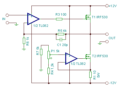
This is classics. And there are commited some audiophile’s “deadly sins”.
First: op-amp in the input stage. It is said, that it causes a lot of distortions, harsh sound and some other problems, but I decided to risk, knowing, that it is the output stage, that controls the harshness / softness of sound. The catalog data of this amplifier say that nonlinear harmonic distortion coefficient of this chip is of the order of 0.003%. Very low.
Second: global feedback loop (resistors R5, R6). It was necessary, because the amplifier was to relay the frequencies as low, as possible, so I had to give up on an output capacitor. Such a capacitor cuts the constant bias output component (very dangerous for the headphones), but also acts as a high bandpass filter and impairs the bass performance. So, capacitors in the signal path destroy the sound quality more than the global feedback loop, which also prevents the constant voltage on the headphones.
The amplifier is powered by symmetric stabilized voltages.
The source load is a classical current source, also made with a MOSFET transistor and an opamp. The idle current of the amplifier is set with the potentiometer P1 while measuring voltage across the resistor R1. For 22 Ohm headphones the current of 185 mA is sufficient. The more current, the amplifier is more resistant to overdrive, but dissipates more heat. The above value of the idle current is fully sufficient for human loudness tolerance.
The amplification coefficient is set by R5 and R6 values by equation: amplification=1+R5/R6. In our example it has the value of 5. It should be chosen dependent on what will be the source of signal for our amplifier.
The capacitor C1 is supposed to prevent the amplifier from high frequency self-oscillations, but it has emerged, that with this capacitor the circuit oscillated at about 2 MHz, after I got rid of this capacitor, the amplifier does not make any trouble.
The MOSFET transistors should be placed on decent radiators because they dissipate lot of heat (several watts). Transistors should be electrically insulated from radiators with mica or silicone washers.
The amplifier consumes about 500 mA on each power branch (+12 and -12 V) and the power source should be able to deliver such a current. Usually the standard application of LM7812 and LM7912 is sufficient, powered by a 2 x 12 V 20-40 W transformer, rectifier bridge and filter capacitors. The voltage regulators also should be heat-sinked and insulated from radiators, similarly as MOSFETs.
Resistor R3 should be placed as close to the transistor as possible.
The circuit was made out of pure curiosity, but the sound showed so high quality and real valve-like “softness”, that it was mounted in an aluminum casing and serves as a part of the electroacoustic set.
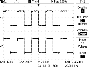
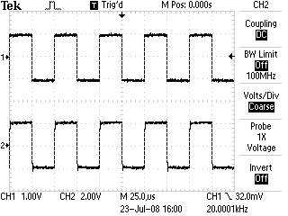
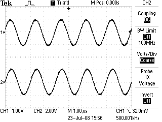
Below we present some oscillograms depicting the amplifier fidelity. The upper graph is the input signal from a generator, the lower one – output signal.
20 kHz, square-wave, gain 2x:
100 kHz, square-wave, gain 2x:
500 kHz, sine-wave, gain 2x:
1 Hz, sine-wave, gain 2x:
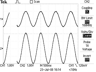
The useful bandwidth reaches above 500 kHz, the square-wave input signal does not cause any ringing, the sound is soft, “valve-like”. As for so simple construction the amplifier is excellent.
Piotr Struski, October 22-nd 2008
您是否曾想过是否可能构建一个高保真度的简单放大器?您是否认为发烧友们声称高品质必须昂贵是正确的?如果是这样,我建议您构建一个简单的A类单端放大器,并用自己的耳朵听听。它具有简单的输出级和最高的音质,不受交叉和其他谐波失真的影响。
MOSFET晶体管使输出的声音类似于真空管。它类似于我爷爷二十多年前听自由欧洲广播的旧收音机的声音。MOSFET晶体管的饱和特性类似于热离子管。
这种设计的主要缺点是其低效率,大约为几个百分点,但耳机只需要几十毫瓦的功率,所以我们可以承受几瓦的能量散发为热量。
电路如下图所示:
这是经典之作。在其中包含了一些发烧友的“致命罪行”。
第一点:输入级中使用运放。有人说它会引起很多失真,刺耳的声音和其他一些问题,但我决定冒险,因为我知道它是输出级控制声音粗糙度/柔和度的因素。该放大器的目录数据显示,该芯片的非线性谐波失真系数约为0.003%。非常低。
第二点:全局反馈回路(电阻R5、R6)。这是必须的,因为放大器要传递尽可能低频的频率,所以我必须放弃输出电容。这样的电容削减了常数偏置输出分量(对耳机非常危险),但它也充当高通滤波器,影响低音性能。因此,在信号通路中使用电容比全局反馈回路更破坏声音质量,后者还可以防止耳机上的恒定电压。
该放大器由对称稳压电压供电。
源负载是一个经典的电流源,同样由MOSFET晶体管和运放制成。通过测量电阻R1上的电压,可以通过电位器P1设置放大器的空载电流。对于22欧姆的耳机,185毫安的电流已经足够。电流越大,放大器对过载的抵抗性就越强,但会散发更多热量。上述空载电流值对于人耐受的音量是完全足够的。
放大系数由R5和R6的值设置,公式为:放大=1+R5/R6。在我们的示例中,它的值为5。它应该根据我们的放大器信号源的选择而定。
电容C1应该防止放大器发生高频自振,但事实证明,使用此电容电路会在大约2兆赫兹的频率上振荡,摆脱此电容后,放大器就不再出现问题。
MOSFET晶体管应放置在体积适中的散热器上,因为它们会散发大量热量(几瓦)。晶体管应使用云母或硅橡胶垫片与散热器电气隔离。
放大器每个电源分支(+12和-12 V)消耗约500 mA,电源应能够提供这样的电流。通常,LM7812和LM7912的标准应用就足够了,由2 x 12 V 20-40 W变压器、整流桥和滤波电容器供电。电压调节器也应散热,并与MOSFET类似地绝缘。
电阻R3应尽可能靠近晶体管放置。
该电路纯粹是出于好奇心制作的,但声音表现出如此高质量和真正的类似真空管的“柔和”,以至于它被安装在铝外壳中,并作为电声设备的一部分。
下面我们呈现一些示意放大器保真度的示波图。上图是来自发生器的输入信号,下图是输出信号。
20 kHz,方波,增益2倍:
100 kHz,方波,增益2倍:
500 kHz,正弦波,增益2倍:
1 Hz,正弦波,增益2倍:
有用的带宽超过500千赫兹,方波输入信号不会引起任何共振,声音柔和,”类似真空管”。对于如此简单的设计,这个放大器非常出色。
Piotr Struski, 2008 年 10 月 22 日